Fuji Electric, High static pressure differential transmitters for Oil & Gas applications
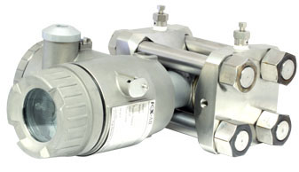
Since 1996, Fuji Electric France has been developing specific differential pressure transmitters for oil applications and which are ideally suited to Topside and Subsea applications (depths down to 3500 metres). Thanks to technology based on a sensitive element which floats in the neck of the cell, our differential pressure transmitters enable flow measurements with the following static pressures:
- 7500 Psi (517 bar)
- 10 000 Psi (690 bar)
- 15 000 Psi (1035 bar)
- 20 000 Psi (1380 bar)


Solutions for specific customer applications
Based on extensive experience of supplying transmitters for Oil & Gas applications, Fuji Electric France, released of its latest Differential Pressure as a direct response to customer’s requirement in high pressure applications that are traditionally found in Oil & Gas flow measurement. The experience and technical capability that Fuji Electric built into the new transmitter enables it to measure differential pressures of 130 mbar at static pressures of up to 15 000 Psi (1035 bar), typically found in top side and subsea applications.
Measuring principle
The transmitter utilizes a unique micromachined capacitive silicon sensor with state of the art microprocessor technology to provide exceptional performance and functionality. The silicon sensor is assembled floating in measuring cell neck, which allows extreme high line pressures and improves the static pressure characteristics.
Robust construction
The design is based on an all welded construction, where the welded assembling of the process covers on the measuring cell replaces the gaskets. Adapted SS 660 bolting and the specific process covers – NACE compatible – ensure that the required mechanical strength to the assembly is certified according to a PED category IV module H1.
Accuracy rating :(including linearity, hysteresisand repeatability)
For spans greater than 1/10 of URL : ±0.1% of span at reference conditions = 22°C ±3°C and atmospheric pressure
Stability
±0.2 % of upper range limit (URL) for 3 years (at reference conditions = 22°C ±3°C and atmospheric pressure)
Ambient temperature effect
Zero : ± (0.1+0.025 x URL / span) in % of URL / 28°C Total : ± (0.125+0.025 x URL / span) in % of URL / 28°C Double the effects for diaphragm material code “H” (7th digit in codes symbols)
Static pressure effect
Standard specifications:
- Zero: ± 0.1 % of URL / 10 MPa
- Hysteresis & repeatability of zero: any value inside the envelop of ± 0,1% of URL/10 MPa
- Span: 0 to - 0.3% of span / 10 MPa
- Double the effects for diaphragm material code “H” (7th digit in codes symbols)
Premium specifications:
- Zero: ± 0.1 % of URL / 10 MPa
- Hysteresis & repeatability of zero: ± 0,1% of URL
- Max zero change = ± 0,15% URL over steps of 10 MPa (curve shape for zero versus static pressure
Supply voltage effect
Less than 0.05% of calibrated span per 10 V
RFI effect
Less than 0.2% of URL for the frequencies of 20 to 1000 MHz and field strength 30 V/m when electronics covers in place. (Classification : 2-abc : 0.2% span per SAMA PMC 33.1)
Mounting position effect
Zero shift : Less than 0.12 kPa {1.2 mbar} for a 10° tilt in any plane. No effect on span. This error can be corrected by adjusting Zero after installatrion.
Vibration effect
< ± 0,25% of spans for spans greater than 1/10 of URL. Frequency 10 to 150 Hz, acceleration 39,2 m/sec2.
Dielectric strength
500 V AC, 50/60 Hz 1 min, between circuit and earth.
Insulation resistance
More than 100 MΩ at 500 V DC
Turn-on time
4 seconds
Accuracy rating
Output
- 50 to 100% : ± 0,1% of span
- 20 to 50% : ± 0,25% of span
- 10 to 20% : ± 0,5% of span
Ambient temperature effect
Shift at 20% output point : ± (0,3 + 0,25 x URL / span) in % of URL / 28°C
Low flow cut-off
Customer configurable for any point between 0 to 20% of output. Process connections
1/4” NPT, autoclave 9/16 - 18 UNF - 2B, others upon request.
Wetted parts materials
Diaphragm SS 316L, Hast.C 276, other wetted parts material : SS 316L, Hast.C 276, Duplex, Inconel 625
Non wetted parts
- Electronics housing : SS 316
- Bolts / nuts : ASTM-A453 Grad 660
Ambient temperature
-10 to 85°C
Process temperature
-10 to 120 °C
Remote seal designs
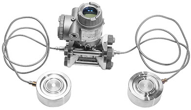
To avoid hydrate formation for subsea applications, remote seals can be assembled on the DP transmitter. Possible process connections via remote seals according API, RTJ standards or according customer design.
- 7500 Psi (517 bar)
- 10 000 Psi (690 bar)
- 15 000 Psi (1035 bar)
- 20 000 Psi (1380 bar)
Ultra-deep water flow measurement
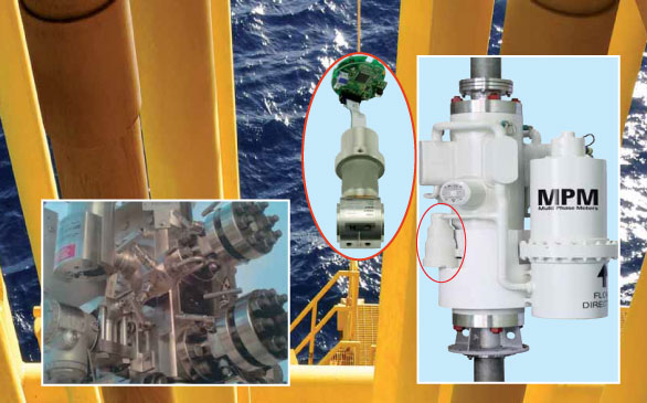
Oil & Gas producers are drilling to new depths to keep up with demand. Single and multiphase flowmeters are challenged by the need to operate at more and more high pressures. Fuji Electric France supplies differential pressure transmitters for multi-phase flow measurement up to 3 500 meter water depth. More than 6000 specific high static pressure DP transmitters from Fuji Electric France are operating all over the world on top-side and subsea applications in the Oil & Gas market.
Fuji Electric high static pressure differential pressure transmitters
Today’s oil and gas industry is creating challenging applications that need specifically designed solutions to cope with higher static pressures, aggressive process and environmental conditions. The experience and technical capability that Fuji Electric France has built into these transmitters enables them to measure differential pressures of 130mbar at static pressures of up to 1 035bar (15 000psi), typically found in top-side and subsea applications. The accuracy and reliability of Fuji Electric’s transmitters is underpinned using specialist calibration equipment that produces differential pressure at extreme static pressures. This equipment is traceable to international metrology standards, through third party verification.
Fuji Electric high performance pressure transmitters FKC Type Differential Pressure (flow) Transmitters for High Static Pressure
The improved specifications of Fuji Electric transmitters provide accuracy, reliability and extended long-term stability : Micro-machined silicon and floating cell technology gives Fuji Electric the ability to manufacture DP transmitters that provide accuracies of up to 0.1% of adjusted span, with a long-term stability of ten years at static pressures up to 1,035 bar. Specific all welded design, the choice of adapted wetted and non wetted parts materials are fitting with NACE requirements and the Pressure Equipment Directive 97/23/EC category IV module H1. Numerous process connection by remote seals are possible : Hub connectors, API, SPO standards or at customer request. Models are available to suit applications that require remote diaphragm seals, digital communications, hazardous area certification, and offshore protection and subsea enclosures.
Solutions for specific customer applications
Based on extensive experience of supplying transmitters for Oil & Gas applications, Fuji Electric France, released of its latest Differential Pressure as a direct response to customer’s requirement in high pressure applications that are traditionally found in Oil & Gas flow measurement. The experience and technical capability that Fuji Electric built into the new transmitter enables it to measure differential pressures of 130 mbar at static pressures of up to 15 000 Psi (1035 bar), typically found in top side and subsea applications.
Measuring principle
The transmitter utilizes a unique micromachined capacitive silicon sensor with state of the art microprocessor technology to provide exceptional performance and functionality. The silicon sensor is assembled floating in measuring cell neck, which allows extreme high line pressures and improves the static pressure characteristics.
Robust construction
The design is based on an all welded construction, where the welded assembling of the process covers on the measuring cell replaces the gaskets. Adapted SS 660 bolting and the specific process covers – NACE compatible – ensure that the required mechanical strength to the assembly is certified according to a PED category IV module H1.
Accuracy rating :(including linearity, hysteresisand repeatability)
For spans greater than 1/10 of URL : ±0.1% of span at reference conditions = 22°C ±3°C and atmospheric pressure
Stability
±0.2 % of upper range limit (URL) for 3 years (at reference conditions = 22°C ±3°C and atmospheric pressure)
Ambient temperature effect
Zero : ± (0.1+0.025 x URL / span) in % of URL / 28°C Total : ± (0.125+0.025 x URL / span) in % of URL / 28°C Double the effects for diaphragm material code “H” (7th digit in codes symbols)
Static pressure effect
Standard specifications:
- Zero: ± 0.1 % of URL / 10 MPa
- Hysteresis & repeatability of zero: any value inside the envelop of ± 0,1% of URL/10 MPa
- Span: 0 to - 0.3% of span / 10 MPa
- Double the effects for diaphragm material code “H” (7th digit in codes symbols)
Premium specifications:
- Zero: ± 0.1 % of URL / 10 MPa
- Hysteresis & repeatability of zero: ± 0,1% of URL
- Max zero change = ± 0,15% URL over steps of 10 MPa (curve shape for zero versus static pressure
Supply voltage effect
Less than 0.05% of calibrated span per 10 V
RFI effect
Less than 0.2% of URL for the frequencies of 20 to 1000 MHz and field strength 30 V/m when electronics covers in place. (Classification : 2-abc : 0.2% span per SAMA PMC 33.1)
Mounting position effect
Zero shift : Less than 0.12 kPa {1.2 mbar} for a 10° tilt in any plane. No effect on span. This error can be corrected by adjusting Zero after installatrion.
Vibration effect
< ± 0,25% of spans for spans greater than 1/10 of URL. Frequency 10 to 150 Hz, acceleration 39,2 m/sec2.
Dielectric strength
500 V AC, 50/60 Hz 1 min, between circuit and earth.
Insulation resistance
More than 100 MΩ at 500 V DC
Turn-on time
4 seconds
Accuracy rating
Output
- 50 to 100% : ± 0,1% of span
- 20 to 50% : ± 0,25% of span
- 10 to 20% : ± 0,5% of span
Ambient temperature effect
Shift at 20% output point : ± (0,3 + 0,25 x URL / span) in % of URL / 28°C
Low flow cut-off
Customer configurable for any point between 0 to 20% of output. Process connections
1/4” NPT, autoclave 9/16 - 18 UNF - 2B, others upon request.
Wetted parts materials
Diaphragm SS 316L, Hast.C 276, other wetted parts material : SS 316L, Hast.C 276, Duplex, Inconel 625
Non wetted parts
- Electronics housing : SS 316
- Bolts / nuts : ASTM-A453 Grad 660
Ambient temperature
-10 to 85°C
Process temperature
-10 to 120 °C
Remote seal designs
To avoid hydrate formation for subsea applications, remote seals can be assembled on the DP transmitter. Possible process connections via remote seals according API, RTJ standards or according customer design.


_series.png)
_series.png)
_series.png)
_series.png)
_series.png)
_series.png)
_soft_starters.png)


.png)


